This post may still be helpful, but I compiled a much more comprehensive reference site for updating Anduril lights at https://anduril.click/.
I have an older SP36 BLF from 2020 that was stuck on Anduril 1 while all my other Anduril lights are on Anduril 2, so I finally decided to rectify that. The SP36 was the last Anduril light I had left on Anduril 1 as it was also the most difficult to update.
Hat tip to /u/Wily_Wapiti for their post about updating their own SP36 which gave me some extra guidance and encouraging information.
Since I compulsively write documentation as I go, here are my notes in case anyone else needs them.
Check the version
There are at least three versions of the board around:
- No flashing pads with ATtiny85, which is what I had and what this guide covers
- Flashing pads with ATtiny85
- Flashing pads with ATtiny1616
The models with flashing pads do not need disassembled the way this guide describes and the update procedure would be different, closer to the procedure for updating the LT1.
Before starting, try to do a version check which is 15+ clicks from off. Write down the result. The last four digits will be a model number which can be looked up in the list in the MODELS file and will definitely tell you what it’s running. If the light is running a version of Anduril before the version check was added, it’s likely the older variant similar to this guide or at least likely has an ATtiny85 and not ATtiny1616. If it outputs a date but no 4-digit model code, it’s almost certainly an older model running Anduril 1.
No matter which model the light is, do a test and a read to save the existing firmware to confirm the correct settings before attempting to write.
Supplies
Here are the items I used:
- Flashing kit from Hank or another usbasp board.
- SOIC8 Clip
- Jumper wires with Dupont connectors
- 5mm Allen wrench/hex key
- Duct tape
Getting to the chip
Follow the disassembly procedure at https://budgetlightforum.com/comment/1556068#comment-1556068
That post has pictures and directions, but to save a click, here is the general idea:
- Unscrew the head from the battery tube
- Use needle nose pliers to unscrew the ring retaining the switch
- Remove the ring and rubber switch cover
- Loosen the switch PCB. If it’s glued you may have to use a tool such as a dental pick to pry it free. Mine was loose/unglued (lucky me!)
- Carefully move the switch PCB out of the way but don’t pull too much on the wires.
- Use an Allen wrench, S hook, bent nail, or similar to put downward pressure on the PCB through the switch hole
- You can see through the switch hole and find a bare spot on the board to press. Careful not to dislodge the the wiring and careful not to press the switch wires into the edge of the switch hole as it can damage them.
- Carefully pry, the glue will eventually come free, but watch where the tool will apply pressure.
- With the PCB loose, check to make sure nothing was damaged when removing the board.
I used a 5mm Allen wrench with duct tape covering the end going inside the light. The advantage of the Allen wrench is you can lift up on the handle and use the “elbow” of the wrench against the switch hole as a fulcrum rather than relying on pushing down or hammering. I used a T handle and some socket adapters to get extra leverage and it popped out after some work.
Something softer than tape on the end might have been better, I scraped the PCB a little but it was on an empty spot so not critical.
Wire up the adapter
- Connect a SOIC8 clip to a usbasp board with jumper wires in the right places
-
Use the pin guide below, adapted from a BLF post
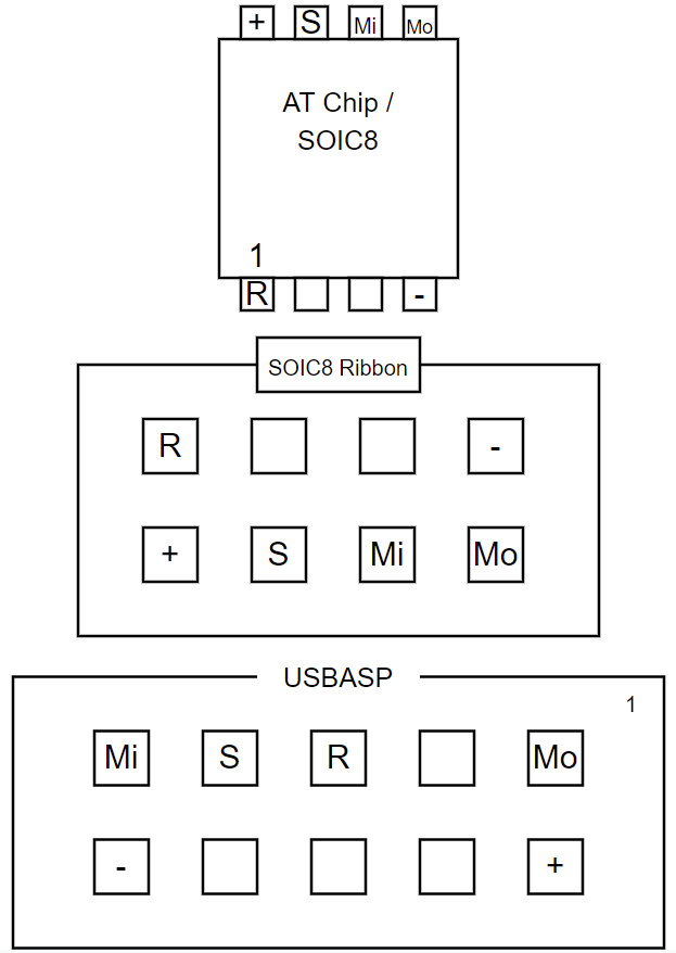
Wiring Diagram for SOIC8 chip, clip, and usbasp board (note location of notches) -
Here are pictures of how I wired up the connection between the usbasp board and the SOIC8 clip:
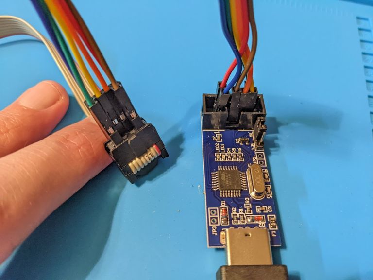
Connection from usbasp to SOIC8 clip (front view) 
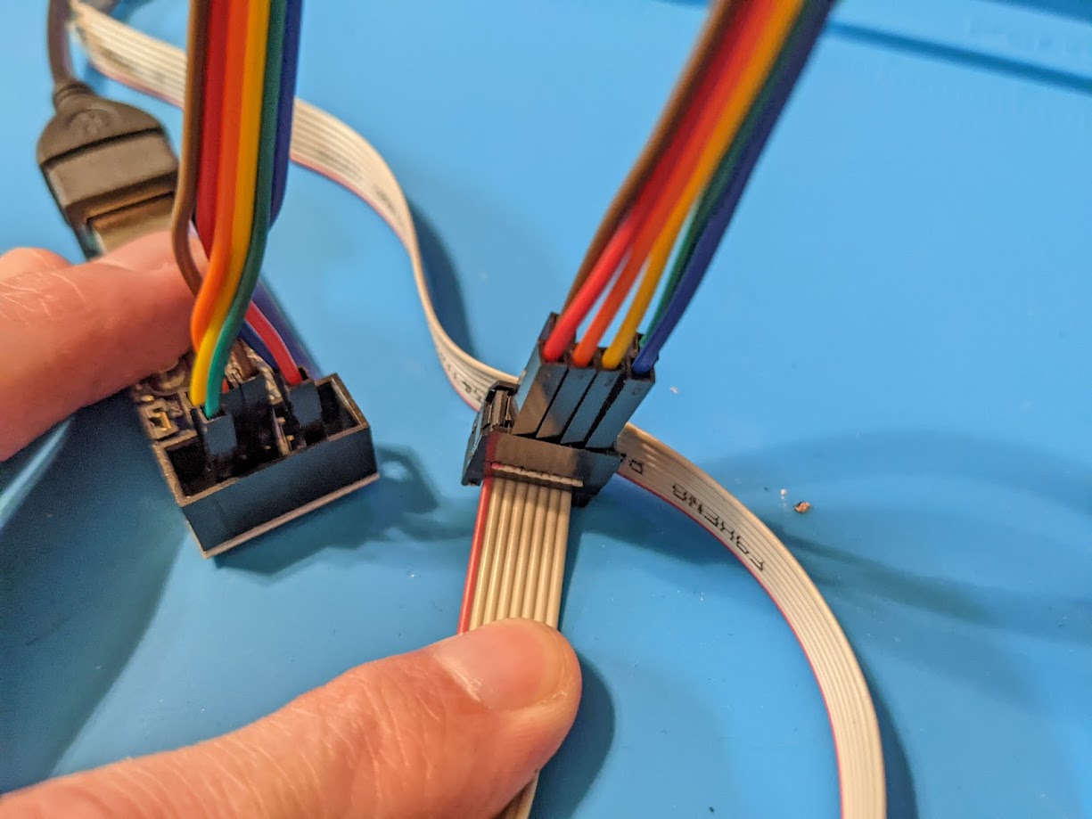
Connection from usbasp to SOIC8 clip (rear view) -
I used jumper wires with M-F Dupont connectors so I could leave the original leads on my SOIC8 clip and plug into its ribbon cable connector.
-
- Connect the SOIC8 clip to the correct chip on the PCB, which is the one adjacent to the USB port. There is a divot on the chip marking pin 1, see the pictures and the pinout guide linked above.

As most of these lights can be updated with a SOIC8 clip, after doing this I crafted a more permanent solution using dupont connector blocks. I used a pick to release the single dupont connectors from the wire ends and inserted them into a 2x4 block for the SOIC8 side and a 2x5 block for the usbasp side. This way I can connect what is now effectively a proper ribbon cable in the future without having to remember or look up the pinouts.
Flash the firmware
-
Download the firmware hex file for the SP36 from http://toykeeper.net/torches/fsm/anduril2/ or compile a new one.
- For older SP36 models this will be
sofirn-sp36.hexand for newer models it may besofirn-sp36-t1616.hex
- For older SP36 models this will be
- Copy the
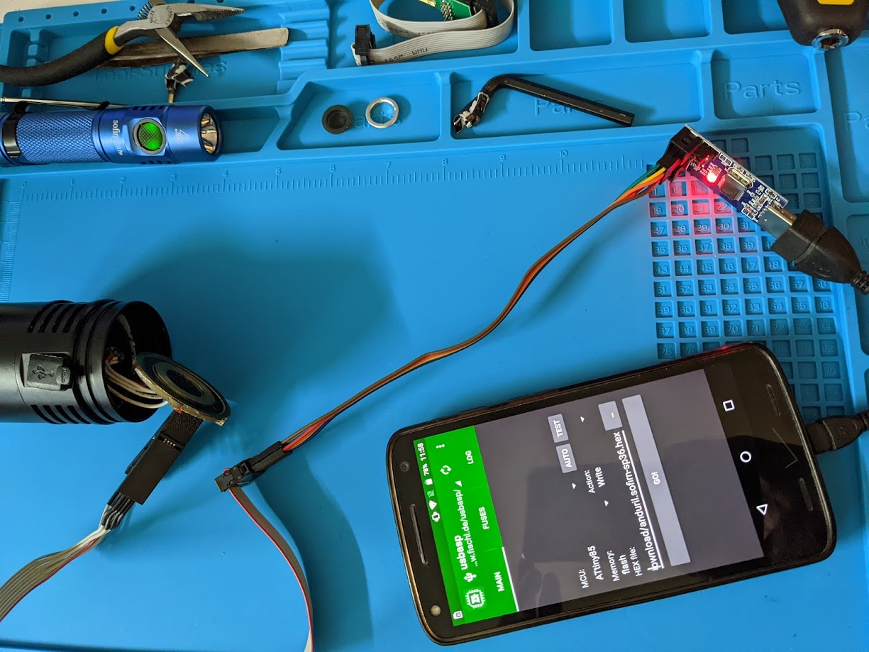
sofirn-sp36.hexhex file to the device which will be doing the flashing. - Connect the usbasp board to whatever you are using the flash the device. In my case this was connected to a phone with a USB OTG adapter.
- I used zflasher AVR
on Android to perform the update, but there are other ways such asavrdudeor similar programs. - The settings I use for zflasher are:
- MCU: ATtiny85 (For newer SP36 models this may be ATtiny1616)
- Memory: Flash
- Read the existing firmware as a separate file (e.g.
sp36-old.hex) and save it somewhere safe (optional, but a good idea) - Write the new firmware to the chip
- Disconnect the SOIC8 clip
Reassemble and finish up
- (Optional) clean up some of the glue residue to make getting the board back in and out easier
- Align the board back up using the USB port and side notches as a guide and gently push it back into place. Odds are it won’t go completely back into place yet.
- Take the batteries out of the tube and screw it back into the head as far as it can go, which should re-seat the board back in place.
- Take the tube back off
- Carefully replace the switch, tucking the wires back inside
- Replace the rubber switch cover and ring
- Tighten the ring back with the needle nose pliers
- Put the batteries back in the tube and factory reset
- Hold the power button down while tightening the battery tube and keep holding it for ~4 seconds after it gets power. Repeat if necessary.
- Enjoy!
Similar Lights
Slight update, I also have a Sofirn Q8 Pro and BLF LT1. The Q8 Pro does not have flashing pads, the LT1 had pads but they didn’t line up with any adapter I have or could make. But in both cases they only had two phillips head screws holding in the driver board. Remove the screws, the board is loose and it was simple to gently turn it over and use the same SOIC8 clip method on them that worked on the SP36.
Line up the USB port and put the screws back in and reassemble, almost easier than trying to hold an adapter up to the pogo pins while running the update.
Adapted from my post on Reddit.